Special projects of course “Architetture dei Sistemi di Elaborazione” since 2018
MP4 files on LandTiger NXP LPC1768
The objective of this project is to extend a previous media player project, based on a custom video format, in order to support standard video files. Since the MP4 standard defines a container which can support a large group of video and audio formats, it is extremely important to select the right ones to include in the project, keeping in mind the low CPU performance (100MHz on a single core) and the limited memory available (only 64KB of RAM). The simplest video codec that can be encapsulated in an MP4 is Motion JPEG, literally formed of a sequence of JPEG images. This format, while not efficient in terms of size, is incredibly fast to decode and only needs enough RAM to store a single frame at a time (or even less, depending on JPEG decoding library). For audio the best solution is FLAC encoding, a lossless format that only requires fixed point arithmetic. Both audio and video quality need to be kept low, since the screen cannot reproduce video larger than about 128×64 pixels and the sound board has a limited depth of 10 bits per sample.
MP4 file structure
MP4 files are composed of a sequence of data containers, called atoms, organized in a tree structure.
The moov atom contains all information needed by a decoder to find and decode a track’s samples, such as offset from the beginning of the file, size, amount of samples per chunk of data, resolution, and audio sample depth.
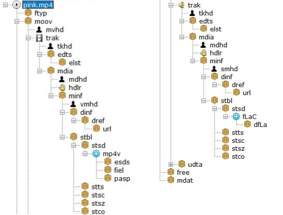
Structure of an MP4 file
This information is split between 4 different tables for each track. Due the lack of RAM available on the board, no table can be fully loaded into memory: they can only be read on demand.
Since moving a file pointer backwards is an extremely slow operation on a FAT partition, 4 different file pointers are needed, 2 for each track, because there are 2 tables of information needed in real time during decoding. This action helped because the two tables are very far from each other, using the same pointer would have involved a continuous back and forward movement of the same with a massive drop in performance.
Encoded data is stored inside the mdat section, with each track split into multiple interleaved chunks.
Video and audio conversion
To convert a video to the supported MP4 version ffmpeg was used, a powerful open source tool, using the following command:
ffmpeg -i INPUT_VIDEO_FILE -vcodec mjpeg -acodec flac -filter:v fps=24,scale=128:64 -strict -2 -ac 1 -sample_fmt s16 -ar 16000 -movflags +faststart OUTPUT.MP4
Arguments
-vcodec mjpeg: select Motion JPEG as video encoding-acodec flac: select FLAC as audio encoding-filter:vspecifies a list of filters to apply to the video streamfps=24: resample the video stream to 24 frames per second (higher values risk not being able to be reproduced in real time, depending on video resolution, since the screen interface is extremely slow. See http://cas.polito.it/NXP-LANDTIGER@PoliTo-University/?p=225 for further explanation )scale=128:64: resize the video to 128×64 pixels (both axes must be multiples of 8, due to the limitations of the decoding library and a total number of pixel greater then 128×64 can generate frame delay)
-ac 1: merge all audio channels into 1, since the board only has one speakersample_fmt s16: reduce the audio sample depth to 16bit (the 6 lower bits are discarded during audio playback but ffmpeg simply can’t generate 10 bit samples)-ar 16000: resample the audio stream to 16000 samples per second (setting it higher than 16000 values may need a buffer resize)-movflags +faststart: write themoovatom at the start of the file in order to make data table reading faster.
Asynchronous reading and reproduction
In a classic media player on a computer, synchronization is generally achieved thanks to a multi thread/process architecture. The LPC1768 is a single core microcontroller, so neither multithreading nor multiprocessing are available, replaced by an asynchronous paradigm based on 4 different timers and a priority system between handlers.
All 4 available timers are used in the project, with the following priority levels from high to low:
- Reproduce the next audio sample, either 44100, 16000 or 8000 times per second depending on the sample rate
- Decode and reproduce a video sample, 24 times per second (or lower, depending on video encoding)
- Read more data (different timers, same priority)
- Fill one of the 2 audio buffer if empty (1/50 the frequency of time 1, about the time to play 50 audio sample)
- Fill video buffer if empty (2x the frequency of timer 2, just to be sure there is always data to process)
The priority value is based on how much a delayed execution would affect the user experience. An audio sample being reproduced for too long would create a distorted and incomprehensible sound, while a slightly lower video update wouldn’t pose a problem.
Conclusion
This kind of MP4 file achieves a compression ratio of about 8:1 compared to the raw file used in the previous version of this project, while keeping the same audio quality and a slightly lower video quality (JPEG compression can generate some video artifacts). While the software can theoretically handle a higher resolution (up to 320×240, full screen resolution), the screen interface is extremely slow, resulting in noticeable video delays for video sizes bigger than 128×64.
Example: https://youtu.be/EjUpucxNXsM
UART – Universal Asynchronous Receiver-Transmitter for LandTiger NXP LPC1768
The most basic method to communicate with different devices is serial communication where you send the bit “in series” one after the other; on the contrary, in parallel communication, bits are sent all at once on different links in parallel channels.
In UART communication, data flows from the Tx pin of the transmitter UART to the Rx pin of the receiver UART.
UART transmits data in asynchronous way, which means that there is no clock signal to synchronize the stream of bits from the transmitter UART to the receiver UART.
How does the receiver know when the incoming data starts, and when it ends?
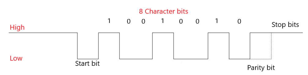
UART communication, instead of a clock signal, need to share a common configuration between the transmitter (Tx) and the receiver (Rx) such as word length, baud rate, parity, start and stop bit.
Parity bit is a method to detect if any data has changed during transmission to the receiver. This is helpful because bits can changed by electromagnetic radiation, or long-distance data transfers. Parity bit can be even parity or odd parity.
The transmitter UART (Tx) adds to the data packet, at the beginning and at the end of the packet, start and stop bits that define when the packet starts and when it ends. These bits are very useful for the UART (Rx) receiver, because it knows when it starts reading data and when it finishes reading it.
Moreover, the transmitter and the receiver need to share the same configuration of the baud rate, which is a measure of the speed of data transfer, which is expressed in bits per second (bps); without knowing the speed, the receiver will not be able to know when one bit will end and when the other one will start.
How can we transfer data with UART?
Before we can transfer data, we need to configure the UART in our LPC1768; UART is based on different registers, each with a specific task.
Receiver Buffer Register – RBR: contains the data received from the serial interface.
Transmit Holding Register – THR: Contains the data to be transmitted.
Divisor Latch LSB register – DLL: contains the lower 8-bit value of the baud rate.
Divisor Latch MSB Register – DLM: contains the upper 8-bit value of the baud rate.
DLL and DLM together form a 16-bit value which is used in baud rate generation.
Line Control Register – LCR: Used to configure the word length (5,6,7 or 8 bits), the number of stop bits and the parity bit (odd, even or no parity).
Interrupt Enable Register – IER: Enable or disable the interrupt request. Interrupts are not generated automatically, but you need to configure the UART to do so.
Interrupt Identification Register – IIR: allow to identify the status of an interrupt request.
What can I do with UART?
With UART you can connect the LandTiger LPC1768 to a terminal (like TeraTerm), where you can send something like text to the board.
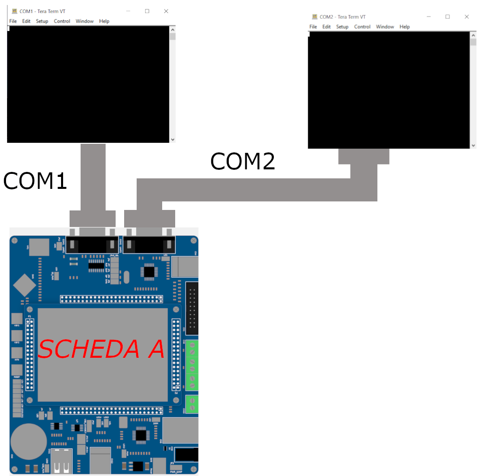
For example, following the schema which is described by the image below, I sent a message from the terminal to the UART0, this is redirected to UART2 which sends it to the other terminal.
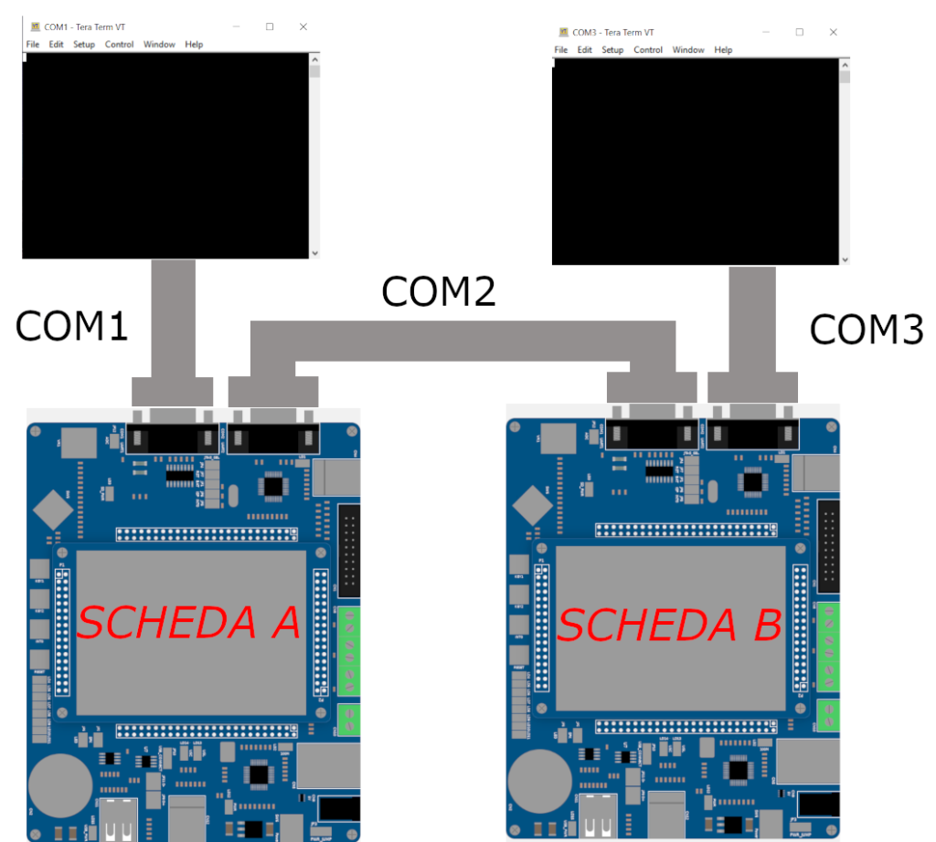
I can also connect two LandTiger. The schema is decribed by the image below.
USB Device Emulation – Adding USB Capabilities to LandTiger Emulator
Hi everyone! In this post I’m going to recap what I did during the last months, trying to expand the functionalities offered by the simulator used in the Computer Architecture course.
I was given the task of implementing a way for the emulator to communicate with the host operating system (in this case Windows 10) via USB. Being USB a very wide and detailed protocol I decided to start from what I had and in particular I focused on the USB HID library already implemented for the LPC1768.
But first, what is USB HID?
USB Human Interface Device class is a part of the USB specification for peripherals that are aimed to interact with human beings, such as keyboards, mice, game controllers etc.
A key point of the HID protocol is that every device must provide a so called report during the first phases of the connection, which consists in an array of bytes in charge of describing the peripheral which is connecting to the PC. A very handy tool I used to generate these reports can be found here, while some other resources to understand how to generate them are here, here and here.
After a bit of experimenting with peripherals I decided to settle with a simple keyboard peripheral to focus more on its emulation.
Emulation sweet emulation
Once the theory has been laid down the next step was to understand what the physical board was doing when programmed to disguise itself as a keyboard by sending the appropriate report. Two phases can be identified: a setup phase, in which the report and some synchronization data such as polling time (in fact the OS is constantly polling the device asking “Do you have something for me?”) and the actual data exchange which in this case corresponds to keystrokes sent from the board.
Simplyfing things, all of this is made by writing values to the USB controller registers, which are memory mapped on the board, the controller then proceeds to send data to the OS by writing into special buffers called endpoints. Since the emulator does not have anything like an hardware controller (It’s a software!) we have to mimic this behaviour in software.
Luckily for us Keil provides a great environment for developing new functionalities for the software environment and things are further simplyfied by Gabriele Filipponi’s great work on modularizing the emulator.
The DLL
So I developed a DLL which is in charge of this: it behaves as the USB controller on the board by intercepting writes and reads done by the emulator on the addresses dedicated to the USB controller and mimicking what the controller did, for example sending data to the OS through API calls.
Here a clarification is needed, we are NOT actually implementing a virtual peripheral, it would have been probably a cleaner solution but also would have required a lot more work since a full working and especially SAFE driver for it would have been needed (maybe one day), instead my DLL already implements simple functions that communicate with the operating system thanks to Windows API when it is needed.
Time for Demos!
CAN bus – high performance communication protocol
The main object of the project was to expand the simulator capabilities in the direction of communication, in particular develop the Controller Area Network. CAN bus communication is an high performance protocol very popular for automotive, industrial environments, and high speed networks as well as low cost multiplex wiring.
Initially I started working on real landtiger boards. The aim of the first part was to create an application that allow the transmission of points written on one board to another one through CAN bus. The second board after receiving points recreates the same drawing on its own display.
What is indispensable:
- 2 x landtiger boards.
- Keil uVision
- Some wires
- 2 x Ulink 2
- 2 x power pack
Expanding simulator capabilites
The second part of the project is related to expand the simulator in order to allow the communication through CAN bus. In order to do so I used C++ and visual studio IDE, keil application note 154 beyond the user manual of the LPC176x.
After more than one instances of the simultor are opened you can choose to interconnect them by means of folders. The idea is to recreate the connection of wires in the real world. Two or more instances that want to communicate have to share the same folder.
In order to differentiate multiple CAN connection I used colors, multiple CAN connected together share the same color beyond the same folder.
For testing purpose the transmission of points is used as on the real boards.
ETHERNET – Emulation of the Landtiger PHY-EMAC peripheral
The aim of this article is to show how is possible to emulate the Ethernet Peripheral through the Landtiger Emulator, on Keil uV5. Thanks to the development of the ethernet emulator, is possible to extend the base functionality of the landtiger emulator.
It supports both incoming connections from the host PC towards the emulated board and board-to-board communication within 2 distinct emulation sessions.
The development of this emulator is possible thanks to the SoC emulation offered by Keil uV5 and its support to additional extensions that can be developed thanks to some exposed APIs.
The structure of the Emulated network
The emulator implements a “virtualized” ethernet LAN accoriding to the following scheme:
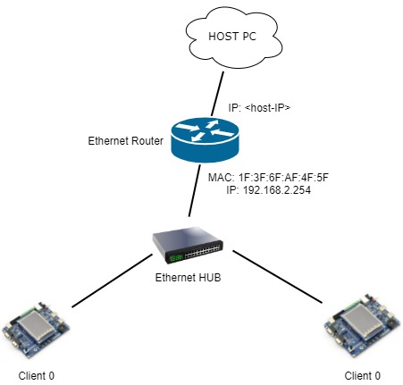
We can see how the router is able to interface the virtualized LAN with the real HOST PC. This is done by opening a local TCP Socket, on localhost::6589, and each incoming packet from the HOST PC towards this socket leads to a new connection between the Router and the Client (the emulated LandTiger board).
The router will create a TCP connection between itself and the client. This is done by executing the classic 3-handshake TCP connect phase (SYN, SYN-ACK, SYN). Before this, an ARP Request is sent in broadcast in order to know the client’s MAC Address.
When the telnet client on the HOST PC disconnects (i.e. closes the session, closes the putty shell, and so on), the router intercepts it and will execute a TCP disconnect phase (FIN, FIN-ACK, ACK) between itself and the emulated client. In this way, the emulated board is ready to accept new incoming connections.
In particular, is important to stress the fact that each incoming connection towards the socket will be always redirected to the emulated client that has IP 192.168.2.154, on port 6589. So it’s important to define these values on your firmware.
The redirect is done by implementing a very simple logic similar (not the same!) to the NAT’s one, the technology we find in our real-world LANs nowdays. Each incoming packet from localhost:<client_port> to localhost:6589 is translated into a packet from 192.168.2.254:6589 to 192.168.1.154:6589.
A working example
Here is the demo. Note how is possible to enable/disable, indipedently for each Keil Project, the ethernet emulation.
The demo shows a simple project that implements a ‘telnet-like server’ on the board. With this developed demo, is possible to connect to it using a classic telnet client and then use some simple commands like echo or a command to show or set one of the GPIO2 pin (the one that controls on-board leds and switches).
In conclusion
Finally, we can simulate the EMAC peripheral that the LandTiger’s SOC offers to us as developers. The code behind it is a bit tricky (it’s not so easy to synchorize a lot of threads!), but at the end it works as expected.
Achieved goals:
- Supports both incoming connections from the host PC towards the emulated board
- Supports board-to-board communication within 2 distinct emulation sessions
For who wants to extend the functionalities offerend by this emulator, here there are a few ideas:
- Support for NAT-like table configuration
- Support for outgoing connections from the board to the host PC
- Drawing in a window all the frames exchanged in the emulated LAN
DISPLAY – Simple LandTiger NXP LPC1768 video player
The aim of this article is to briefly explain how to play a short video (in terms of sequence of frames) using the LandtTiger LPC1768 board and the connected ILI9325 LCD screen (ILI9320 on some board).
First of all we need to find out a way to convert an input video in a compatible format. In order to do that, the most direct way – and the one we will take – is to extract a sequence of frames from it and then print those extracted frames to the screen, with specific delay constraints.
Extracting frames
For this purpose the choice fell on ffmpeg – an extremely powerful tool that converts and edits audio and video streams.
After installing it, let’s extract a resized portion of the input video
ffmpeg -i INPUT_VIDEO -vf scale=”-2:HEIGHT,crop=WIDTH:HEIGHT” -ss START_TIME -t DURATION “VIDEO_NAME_cut.mp4”
where the non-obvious parameter are WIDTH and HEIGHT since:
- in the first part you can omit one of the two (by replacing with a -1 or -2 as appropriate)
- in the crop part they must be consistent with the scaled down size above specified
Now let’s actually extract the frames
ffmpeg -i “VIDEO_NAME_cut.mp4” -vf fps=1/FRAME_OFFSET -vcodec rawvideo -f rawvideo -pix_fmt rgb565be -f image2 ./$filename%03d.raw
I will explain in detail some of the arguments of the previous command:
- fps=1/FRAME_OFFSET -> “take a frame from source every FRAME_OFFSET seconds”
- rawvideo -> no header inserted, only pixel representation
- -pix_fmt rgb565be -> the flow of data from the Board to the LCD is – #in theory – 16-bit based. What we are asking here is “I want every pixel to be represented in RGB 16 bit convention – Big Endian” [more here]
- output frames will be saved with the .raw extension and with increasing numbers in the filename
Image conversion
Now that we have in our folder a bunch of .raw frames, the next step is to convert them into a C-like structure, that will be imported into our project.
As shown in a previous Special Project (thanks to Gianni Cito), the free and open source image editor GIMP comes to our rescue since it has “Source Code” as output format for our input image. Unfortunally – unless we master the GIMP’s Script–Fu scripting language – this is a time-consuming operation and does not allow us to convert multiple images all at once.
We already have, instead, a partial conversion, i.e. a flow of bytes that can be converted in a C array with the following commands
find . -name “*.raw” | xargs -r -I{} cat “{}” > video_merged
xxd -i video_merged > array.h
The former one merges all the frames into a big file – that somehow represents our video – while the latter makes a dump of the input file and finally generates the .h array!
Ok.. and now?
After this long conversion phase, what we have is an array of unsigned char[] 16-bit value and we want to make it a const char[] one.
Why const?
Because the LandTiger LPC1768 has 512kB of Read-Only flash memory – which is a relatively large amount of memory – that we can use instead of filling the code memory.
How does it work?
- Import the converted .h array
- Create a video object from it
- Set the appropriate RIT interval value
- Enable RIT
You can find the code, the implementation details and an explaination of the import operations on the GitLab repository.
More about timing
In point 3) I said that we must find a proper value for the RIT initialization. A strict timing must be respected in order to obtain an acceptable video playback.
First of all, we need to wait a certain number of milliseconds between two consecutive frames, given by input video’s fps.
For example, a 25fps video will lead to a 40ms delay between frames.
Then, we need a fast way of transferring the frame’s byte stream to the LCD. The GLCD library comes with a LCD_SetPoint function, which accepts the X-Y coordinates and the 16-bit color value as parameters, but it is too slow for video playback purposes! In fact, what it does is to perform three writes to the LCD, two for the indexes selection (to LCD’s registers R20h and R21h) and one for the output RGB value (R22h).
Please note that each write actually hides a double write to LCD (one to the IR index register and one with the actual value). Furthermore, although the ILI932X LCD contemplates a 16-bit interface, the way it is connected to this board does only allow a 8-bit transfer (only 8 out of 16 pins connected).
Definitely, we need to dig into the LCD manual in order to find a faster (and more constant in terms of delays) way of transferring pixels.
Luckily, ILI932x LCD offers a Window Address Area mode, that allows the user to select a subset of the screen. By writing to the R50-53h registers we set the four corners coordinates. Finally, we can send all the frame’s pixels by performing a single index register write (R22h: data transfer) and a flow of pixels transfer. Refer to the following picture
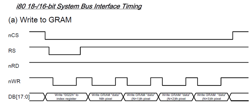
LCD_SetPoint we would have needed at least 5 writes between each consecutive pixel (not taking into account the 16-bit interface problem)Showcase
In conclusion
A few other words to summarize our results and outline some open problems.
We’ve managed to display a short sequence of frames so as to give us the feeling of a video. The conversion sequence is automatic so that we can start it and import everything inside our project.
You are supposed to launch the commands on a Unix/Linux distribution, even if there are tools that make them available on Windows too.
✅Achieved goals
- Video playback
- Convert input video
- Chance of zooming in the image (there will be losses on quality though)
❌ Limitations
- Unfortunately, the 512kB flash memory is big enough to only fit small informations (basically a sequence of some dozens of 50×50 px frames)
- Long Board flashing times
- Complex inclusion operations: we need to include the headers and re-compile every time
📽️ We have overcome these limitations with our improved Audio Visual player, in which the SD card is used to load any pre-converted video and a – – somehow complex and tailored – synchronization between audio and video allows the correct playback (in a slightly higher resolution)!
Federico Bitondo, s276294
Prof. Paolo Bernardi
PoC – Emulation of LCD and TP for the LandTiger board
Hi, my name’s Gabriele Filipponi, I’m making this write-up to demonstrate a proof of concept I made a while ago to emulate the LCD and Touch Panel drivers.
As you know, Keil offers a lot of debug utilities to monitor the cores peripherals on board, but it certainly lacks the ones that we were getting used during the course ‘Architettura dei Sistemi di Elaborazione’ like for example the LCD and TP.
The emulation was achieved with a Python script and a library made by Keil’s developers named ‘UVSC.dll’ that offers a network based interface to control Keil.
For the demo I wrote a simple project that displays a RED background with a label in the center ‘LCD Emulation’ and two buttons at the bottom:
- “Red”
- “Black”
Depending which one you tap it makes the screen RED or BLACK.
Here it is the demo:
Leggere e scrivere EEPROM tramite terminale
La prima cosa da fare per utilizzare il Firmware in questione è scaricare ed installare Tera Term, un emulatore di terminale. Lo si può scaricare dal seguente link:
https://osdn.net/projects/ttssh2/releases/
È sufficiente seguire l’installazione standard affinché tutto funzioni perfettamente.
1- Caricare il firmware
Il primo passo da fare è quello di caricare il firmware EEPROM_TeraTerm (
http://cas.polito.it/gitlab/nxp-landtiger/flash-debug-boot/flash-debug-boot-libraries/tree/master )sulla scheda LandTiger interessata. Quest’operazione è fattibile tramite l’IDE Keil, o con programmi alternativi come Flash Magic (che tuttavia richiedono un file .Hex o .Bin risultato dalla compilazione del firmware in questione). Nel secondo caso è possibile trovare una guida qui.
2- Collegare la scheda al pc
Per collegare la scheda è sufficente il cavo di alimentazione ed un cavo seriale di tipo USB-RS232, come mostrato nel seguente video:
3- Configurare Tera Term
Si può dunque passare alla configurazione del terminale.
Avviando l’emulatore dovrebbe automaticamente aprirsi una finestra di questo tipo:
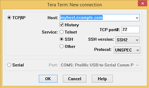
Se così non fosse, è sufficiente cliccare su File-> New connection sulla toolbar.
Occorre spuntare Serial (in quanto vogliamo utilizzare la comunicazione seriale) e selezionare la porta COM che si intende utilizzare (nel caso sia attaccato un solo dispositivo dovrebbe essere presente una sola opzione, in tal modo si evita di dover andare a cercare il numero della porta in Gestione Dispositivi).
È possibile che, selezionando la porta COM, l’opzione sia di questo tipo:

In tal caso è necessario scaricare dei driver per la scheda.
Scaricare l’archivio presente al seguente link: https://drive.google.com/open?id=1n1AgineIVBQal4hmfCIWVmbBKXx9b6Id
decomprimere la cartella e avviare l’eseguibile presente all’interno.
Una volta completati i passaggi di installazione andare in Gestione dispositivi e cercare la porta COM interessata (se non fosse presente la voce Porte( COM e LPT) andare sulla toolbar Visualizza-> Mostra dispositivi nascosti).
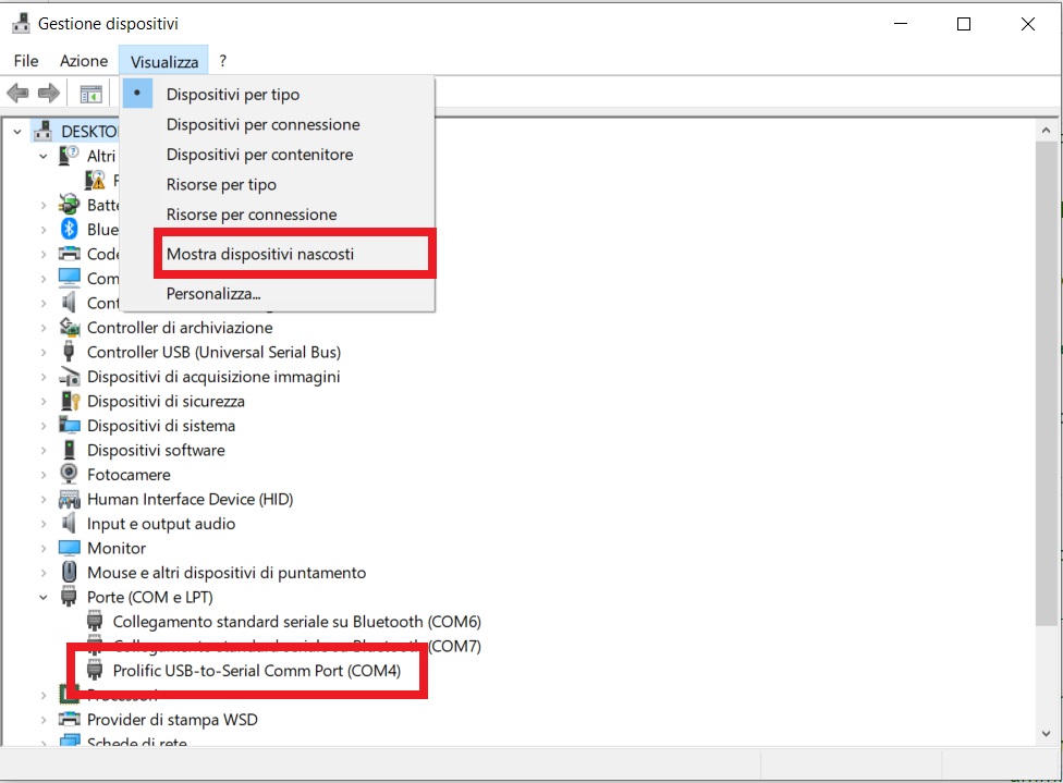
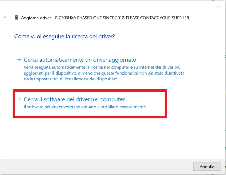
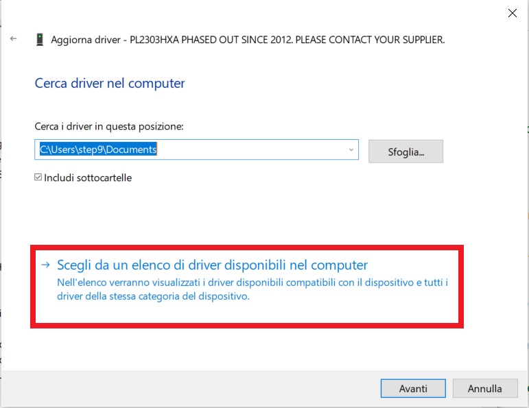
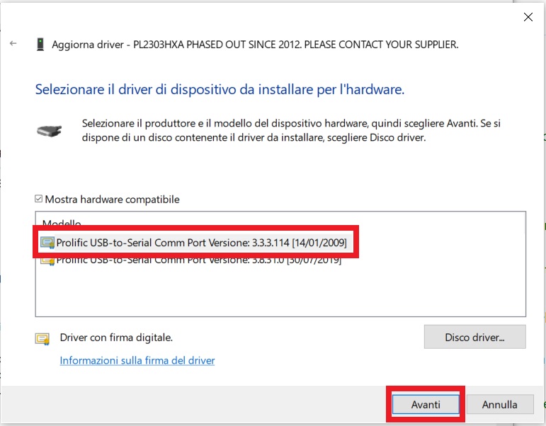
Premere con il tasto destro la periferica e selezionare aggiorna driver -> “Cerca il software del driver nel computer” -> “Scegli da un elenco di driver disponibili nel computer”, selezionare la versione 3.3.3.114 e procedere.
A questo punto dovrebbe comparire la corretta opzione nel menu a tendina di TeraTerm.
Bisogna impostare i corretti parametri riguardanti la trasmissione come in figura:
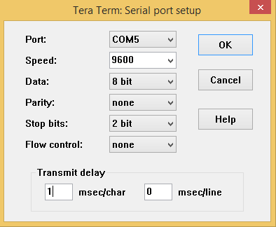
Tutti i valori sono già predefiniti, esclusi Stop bits e Transmit delay.
4-leggi e scrivi la tua eeprom
Tutto è ora pronto per comunicare con la propria EEPROM, è sufficiente premere il tasto reset sulla Land Tiger (il primo partendo da destra) e dispositivo e terminale inizieranno a comunicare.
L’ultilizzo del firmware è molto intuitivo in quanto il menu specifica in ogni momento cosa è possibile fare; vediamo di seguito un breve riassunto:
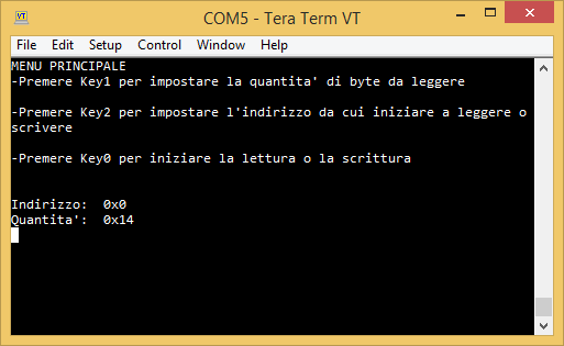
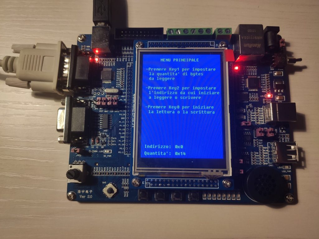
MENU PRINCIPALE
Dal menu principale è possibile modificare il valore dell’indirizzo di partenza della lettura o scrittura, e, nel caso si voglia leggere anche la quantità di bytes che si intende leggere. La terza opzione è quella di spostarsi nel menu di effettiva lettura/scrittura.
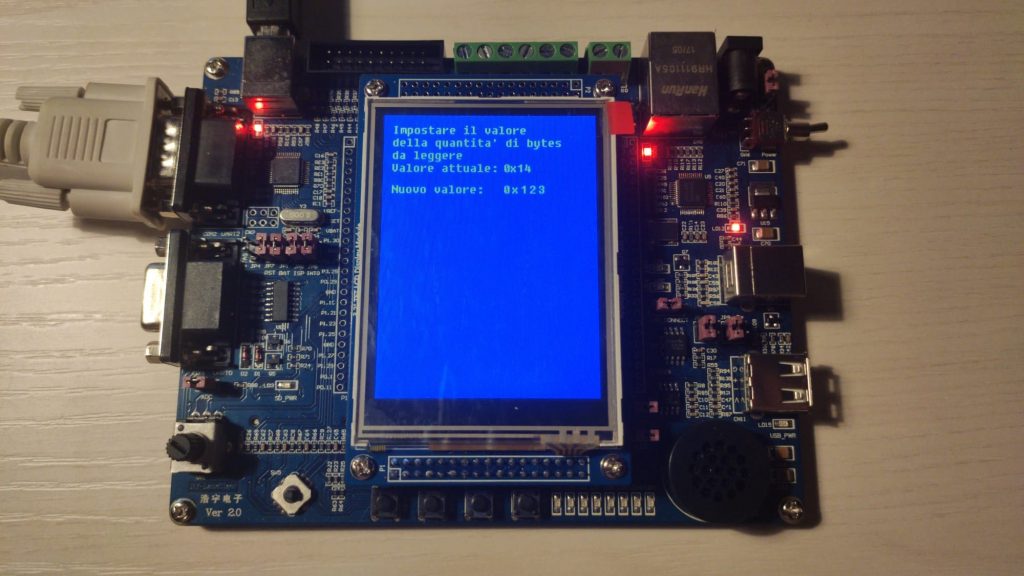
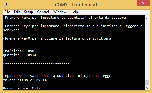
MODIFICA DEI PARAMETRI DI LETTURA/SCRITTURA
Dal menu principale premendo i tasti key1 e key2 modificano i parametri.
sono accettati sia valori decimali che esadecimali (nella forma 0x123).
LETTURA
Dal menu principale, premendo key0 e successivamente key1, sulla base dei parametri precedentemente impostati verranno visualizzati i valori della EEPROM sia sul terminale che sul LCD della LandTiger.
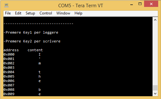
SCRITTURA
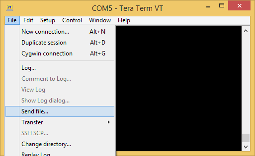
Dal menu principale, premendo key0 e key2 si entra in modalità scrittura. Qualsiasi cosa scritta sul terminale viene scritta sulla EEPROM. Nel caso in cui si debba scrivere un numero elevato di celle, è possibile preparare in precedenza un file .txt e selezionarlo tramite TeraTerm (FILE-> send file).
In qualsiasi parte del menu ci si trovi, premendo key0 è possibile tornare al menu principale (escluso ovviamente il caso in cui ci si trovi nel menu principale stesso).
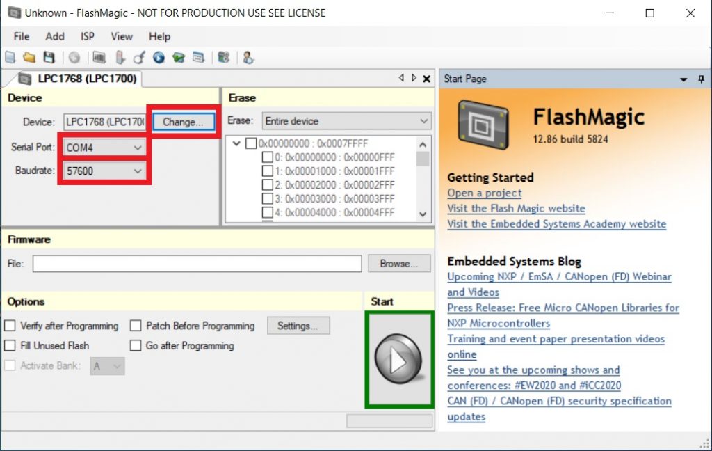
Flash Magic- Breve Guida
Installazione
Flash Magic è un software che permette di programmare microcontrollori tramite comunicazione seriale.
È possibile scaricarlo al seguente link: http://www.flashmagictool.com/download.html
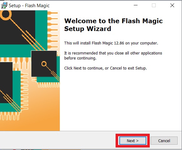
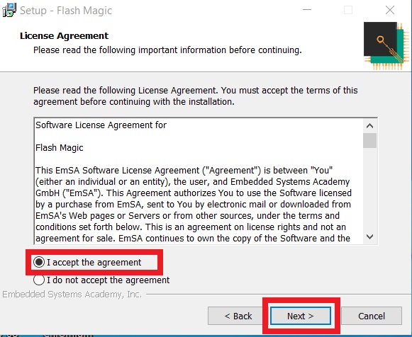
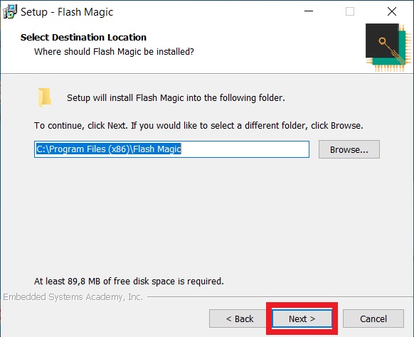
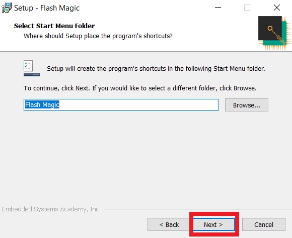
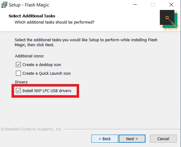
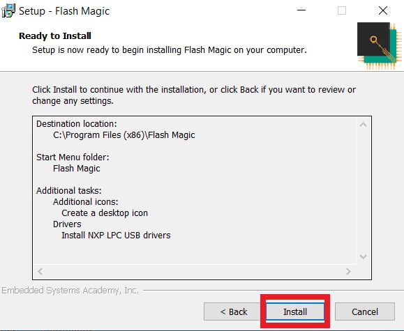
La proccedura di installazione è molto semplice ed intuitiva: è sufficiente cliccare next, accettare i license agreement, scegliere la cartella in cui installare Flash Magic e, molto importante, spuntare la casella “Install NXP LPC USB drivers”; successivamente cliccare next e install.
È Necessario infine installare i device driver tramite il wizard che compare, cliccando avanti e fine.
Configurazione
Si può dunque avviare Flash Magic e iniziare a configurarlo: per prima cosa è necessario selezionare il dispositivo con cui si vuole comunicare; per farlo basta cliccare sul pulsante “Change” tramite il quale si aprirà una finestra che contiene un elenco dei dispositivi previsti. Nel nostro caso si dovrà selezionare “LPC1768”, sotto la sezione “UART”.
Connettere dunque la scheda al computer sia tramite alimentazione che tramite un cavo USB-RS232, connesso alla UART0 del nostro dispositivo.
Un breve video mostra come collegare la scheda:
Selezionare dunque la Porta seriale a cui si è collegati. Occorre andare in Pannello di controllo >Gestione dispositivi. Nella toolbar selezionare “visualizza” e “mostra dispositivi nascosti”. Cercare la voce Porte (COM e LPT) e verificare quale porta si sta utilizzando, infine selezionarla dal menu a tendina di Flash Magic.
Cliccando tasto desto sulla Comm Port e andando su proprietà->Impostazioni della porta è possibile verificare anche il baudrate: anche questo va impostato nel menu a tendina di Flash Magic
Nel caso in cui non sia possibile vedere alcun “USB-to-Serial Common Port” ed apparisse un campo del tipo:
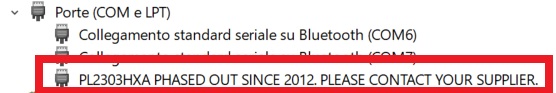
allora diventa necessario fare un passaggio in più:
scaricare l’archivio presente al seguente link: https://drive.google.com/open?id=1n1AgineIVBQal4hmfCIWVmbBKXx9b6Id decomprimere la cartella e avviare l’eseguibile all’interno; una volta completati i passaggi di installazione, tornare alla finestra di gestione dispositivi, premere con il tasto destro la periferica interessata e selezionare aggiorna driver -> “Cerca il software del driver nel computer” -> “Scegli da un elenco di driver disponibili nel computer”, selezionare la versione 3.3.3.114 e procedere.
La periferica dovrebbe a questo punto essere riconosciuta.
Si può procedere dunque selezionando la porzione di memoria da cancellare (Entire device, Sector used by file e Choosen sectors). Per caricare un nuovo firmware selezionare la prima opzione.
Selezionare a questo punto il file .Hex che si intende scrivere nel microcontrollore cliccando su browse nella sezione firmware .
Dopo aver spuntato le opzioni a cui si è interessati, cliccando Start si avvia la comunicaizone che porterà alla scrittura del file .Hex precedentemente selezionato sulla nostra scheda. Il processo potrebbe impiegare qualche minuto, questo è dovuto al fatto che la connessione seriale è discretamente più lenta rispetto alla connessione con Jtag. Si può tuttavia aumentare il baud rate andando su Gestione dispositivi e cliccando tasto destro sulla porta COM interessata -> proprietà -> impostazioni della porta -> avanzate.
TOUCH SCREEN – Creating a Graphics Interface handling Images, Buttons and Drawing functionalities on LandTiger
Gianni Cito: s261725@studenti.polito.it
Prof. Paolo Bernardi: paolo.bernardi@polito.it
The goal of this project is to design an application where it can be exploited some of the graphics features available on the LandTiger. Basically, we are going to see how to create a GUI interface on our LCD screen setting and labeling images, text and buttons in a specific position of the . Once provided this initial theoretical points, we will move to the creation of a drawing scene where we can draw freehand lines or text, change colors, draw lines, circles and rectangles.
Let’s start describing the points that we are going to see to reach the final goal.
Calibration
The first window that appears in our application is the ‘Calibration’ one. This part of the application is extremely important to calibrate the Touch Panel touching some targets plotted on the screen.
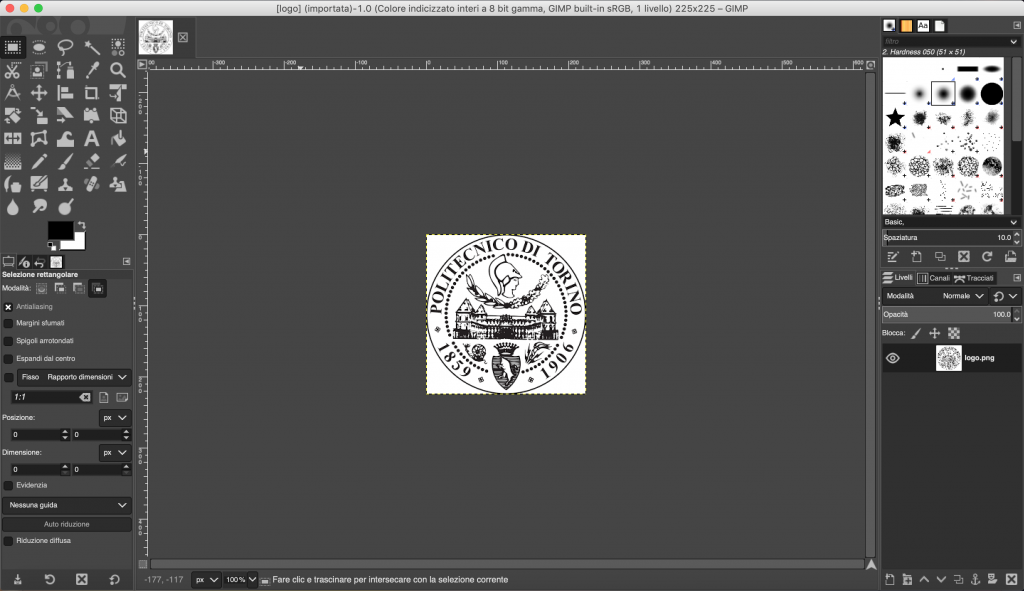
Images
Let’s see how to show images in the LCD screen, as in the above picture.
To import any kind of image inside the application, first of all, we need to convert it in an .c file. To do that we simply use GIMP, an open-source graphics editor. So, let’s see step by step how to convert any image in any format to a .c image file.Import an image in GIMP
- Import the image in GIMP
2. Then, File > Export as and in the dialog that appears, select Source Code which has as extension the c files.
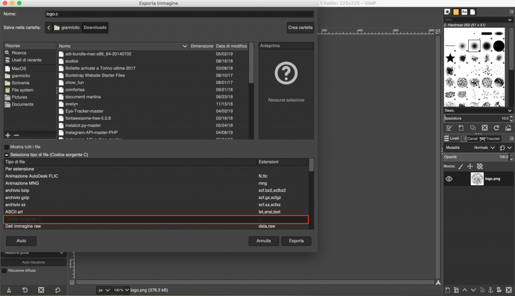
3. In the new dialog, enter a prefixed name, check “Use macros instead of stuct” and “Save as RGB565 (16-bit)” and then hit “Export“.
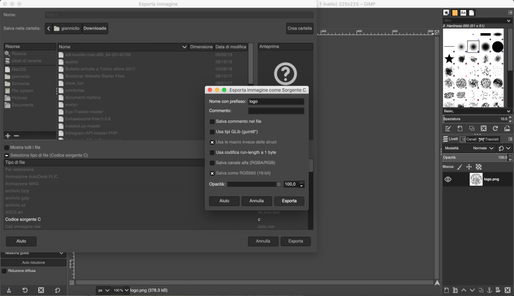
4. Now a .c file is created and look like this:
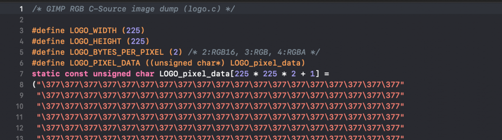
Since the data are static, we can include the .c file inside the location where we want to use the image (#include “image.c”) and then refer the expected BITMAP to the static variable, in our case LOGO_pixel_data.
Buttons
In order to create buttons, I locate an image in the position that I want and then I stored in a linked list the coordinates of the image edges. Doing this, once a click on the Touch Panel will be caught, a function specially created will try to define where a button will have been clicked or not just checking if the coordinates are within the boundaries of the image.
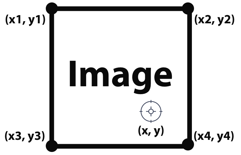
In the above image, we can see the image boundaries coordinates (xN, yN) stored in the linked list needed to detect if the click, depicted by the coordinates (x, y), are inside or outside the image.
Drawing Scene
The drawing scene is the most important scene of this project. Many of the graphics functionalities are used and described right in this scene. We will see how to:
- draw freehand with a brush;
- use a rubber to erase content from the screen;
- draw predefined shapes, likes circles, rectangles or lines;
- change color of the next points that we are going to draw on the screen.
To use one of the functionalities listed above, we need just to press on the buttons depicted in the topbar. A button will be selected when a border appears around it.
Brush
With the Brush we can simply draw on the screen freehand, as depicted in the following screenshot.
Rubber
With the Rubber, instead, we can erase the content already drew on the screen.
Dropdown Menu
Inside the Drawing Scene, that we will see in the next chapter, I also added some dropdown menus to show some further options which belong to the same category, like Circles, Rectangles and Lines belongs all to the Shapes category. The same thing happens for colors.
Pressing for few seconds on buttons with a small arrow on bottom, we can see that a menu appears from the top to the bottom of the screen, giving to the user the possibility to choose one of the other options provided.
An important functionality that I implemented in the dropdown menu is that if the pixels that will be replaced by the dropdown menu are not empty, their content will be stored before showing the menu and then restored before it will disappear.
Lines
To draw a perfect line, you need just to press on the screen two times. The first time for the first point and the second time for the second one. A line will appear joining the two points chose.
To draw lines, I chose the Bresenham’s algorithm and I adapted it to this project.
Circles
To draw circles, as lines, you need to press on the screen two times choosing two points. This time, the first point will be the center, while the second one will be the radius from the center.
Rectangles
To draw rectangles, as for the previous shapes, you need to press on the screen two times. The first point detected will be the top-left edge point, while the second one will be the bottom-right edge point. With these two points, draw a rectangle is very easy. We will use top and bottom coordinates to draw vertical lines, and left and right coordinates to draw horizontal lines.
Colors
The colors menu, allows the user to choose what color use to draw.
As we can see from the above screenshot, the dropdown menu shows 6 colors. These ones are not represented by 6 different drops images filled by different colors, but we have just a single image reused for all the colors.
To do this, I used a movie technique, that is the green screen technique. Using a drop image, filled of red (any color is fine as long as it is different from white and black, because background is white and the borders of the drop are black), we can replace the color we choose with someone we want. I created a specific function to perform this operation, that when encounter the color to replace, it changes to that one desired.