The most basic method to communicate with different devices is serial communication where you send the bit “in series” one after the other; on the contrary, in parallel communication, bits are sent all at once on different links in parallel channels.
In UART communication, data flows from the Tx pin of the transmitter UART to the Rx pin of the receiver UART.
UART transmits data in asynchronous way, which means that there is no clock signal to synchronize the stream of bits from the transmitter UART to the receiver UART.
How does the receiver know when the incoming data starts, and when it ends?
UART communication, instead of a clock signal, need to share a common configuration between the transmitter (Tx) and the receiver (Rx) such as word length, baud rate, parity, start and stop bit.
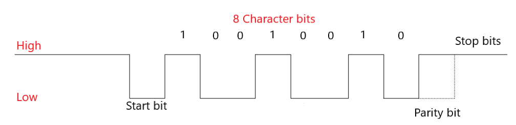
Parity bit is a method to detect if any data has changed during transmission to the receiver. This is helpful because bits can changed by electromagnetic radiation, or long-distance data transfers. Parity bit can be even parity or odd parity.
The transmitter UART (Tx) adds to the data packet, at the beginning and at the end of the packet, start and stop bits that define when the packet starts and when it ends. These bits are very useful for the UART (Rx) receiver, because it knows when it starts reading data and when it finishes reading it.
Moreover, the transmitter and the receiver need to share the same configuration of the baud rate, which is a measure of the speed of data transfer, which is expressed in bits per second (bps); without knowing the speed, the receiver will not be able to know when one bit will end and when the other one will start.
How can we transfer data with UART?
Before we can transfer data, we need to configure the UART in our LPC1768; UART is based on different registers, each with a specific task.
Receiver Buffer Register – RBR: contains the data received from the serial interface.
Transmit Holding Register – THR: Contains the data to be transmitted.
Divisor Latch LSB register – DLL: contains the lower 8-bit value of the baud rate.
Divisor Latch MSB Register – DLM: contains the upper 8-bit value of the baud rate.
DLL and DLM together form a 16-bit value which is used in baud rate generation.
Line Control Register – LCR: Used to configure the word length (5,6,7 or 8 bits), the number of stop bits and the parity bit (odd, even or no parity).
Interrupt Enable Register – IER: Enable or disable the interrupt request. Interrupts are not generated automatically, but you need to configure the UART to do so.
Interrupt Identification Register – IIR: allow to identify the status of an interrupt request.
What can I do with UART?
With UART you can connect the LandTiger LPC1768 to a terminal (like TeraTerm), where you can send something like text to the board.
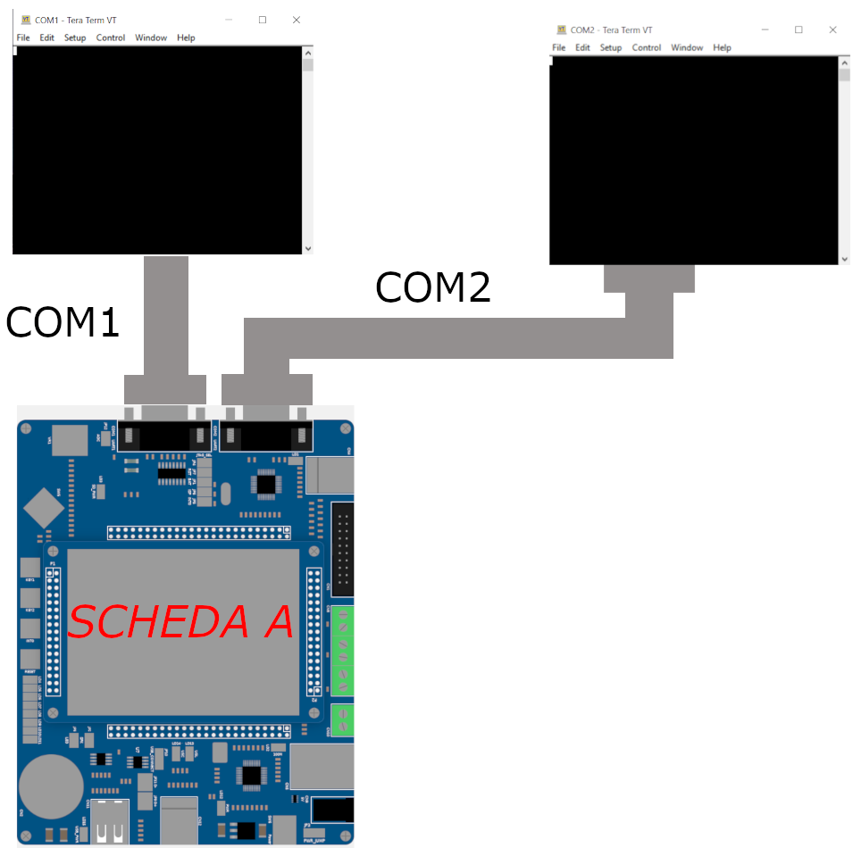
For example, following the schema which is described by the image below, I sent a message from the terminal to the UART0, this is redirected to UART2 which sends it to the other terminal.
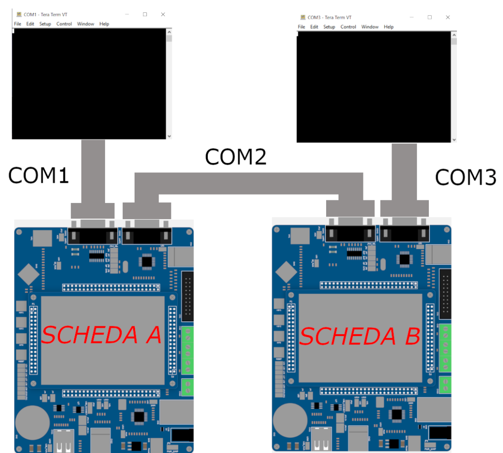
I can also connect two LandTiger. The schema is decribed by the image below.