Led modulation though the Pulse Width Modulation peripheral with adjustable duty cycle and frequency of the PWM signal on a LanTiger V2.0 NXP-LPC1768 Development Board.
Polytechnic of Turin, A.Y. 2019/2020.
Prof. Paolo Bernardi paolo.bernardi@polito.it
Francesco Angione s262620@studenti.polito.it
The goal of this project is to understand the behaviour of a PWM peripheral and appreciate it driving a LED with its output signal.
The starting point has been the following figure:
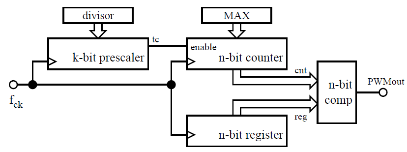
A simplified schema of a PWM peripheral
From which the following formulas can be derived:
- fpwm= fclk/(divisor+1)(max+1)
- duty cycle = reg/(Max +1)
Note: divisor and max are considered as binary values, thus, a one in this formulas has been added.
Those formulas are used in the software in order to change the duty cycle and the frequency accordingly.
In order to achieve that, every fifty milli seconds the ADC is triggered and the value of joystick is sampled. As consequence, the interrupt handler of the ADC will obtain the digital value of the voltage on the potentiometer using it as new value of the duty cycle. Meanwhile, the joystick will be in charge to increase or decrease the frequency of the output signal of the PWM peripheral. Nevertheless this continuous acquisition of the values might be stopped pressing Key 1, freezing the acquisition and locking the duty cycles and the signal frequency to the current ones.
For making the application more user friendly, a simple Graphical User Interface has been added in order to have an instantaneous feedback about all the acquired values and the operations that could be performed on the provided LCD.
As last step, the Led Modulation has been migrated from a simple bare metal project to a one power by a RTOS ( Real Time Operating System ) in particular the Micrium-C/OS III has been used.
In order to achieve that, the operating system has been “ported” to the LandTiger evaluation board.
After that, the previous application has been splitted in three main tasks, the GUI task ( with the highest priority ), and the other ones for the ADC trigger and the sampling of the joystick.
The tasks for the ADC and the joystick have the possibility to wake up the GUI task in order to update the values on the LCD screen everytime they detect a variation.
Reference:
– LPC1768 manual UM10360 Chapter 24: Pulse Width Modulation
– LPC1768 manual UM10360 Chapter 9: General Purpose Input/Output
– LPC1768 manual UM10360 Chapter 29: Analog to Digital Converter
– LPC1768 manual UM10360 Chapter 22: Repetitive Interrupt Timer
– µC/OS-III The Real Time Kernel, Jean J. Labrosse, Freddy Torres
Link to GitLab Repository ( bare metal )
Link to GitLab Repository ( Led Modulation with Micrium – C os III )